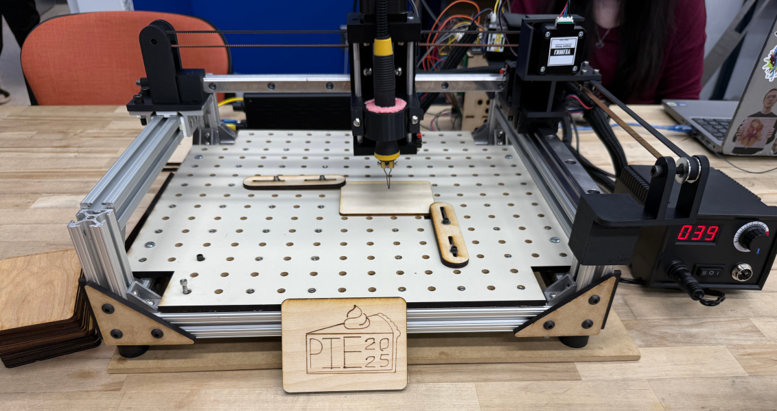
CNC Wood Burner
Skills Used: Onshape, CNC Gantry Design, Stepper Motor Integration, GRBL Motion Control, Fusion 360 CAM, Laser Cutting, 3D Printing, Mechanical–Electrical Integration
Project Description
A custom 3-axis CNC pyrography machine that burns vector designs into wood using a heated tool. Built as the final project for Principles of Integrated Engineering (PIE), the system integrates mechanical design, fabrication, motion control, and CAM into a single automated platform.
Problem
Our team designed and built a CNC-controlled wood burning machine capable of automatically engraving patterns, text, and images onto wooden surfaces. Unlike a conventional CNC router, pyrography requires consistent contact force and careful vertical control to maintain uniform burn depth without damaging the tool or workpiece.
The primary challenge was to design a rigid, repeatable motion system that could safely integrate a heated tool, while staying within strict fabrication, time, and budget constraints ($250).
Method
Mechanical System
The machine uses a Cartesian gantry architecture designed for stiffness, modularity, and ease of iteration:
- 80/20 aluminum extrusion frame and gantry
- HG-series linear rails and bearing blocks for smooth X/Y motion
- Laser-cut MDF baseboard with a configurable mounting pattern
- 3D-printed PLA components for motor mounts, pulley supports, and burner holder
All mechanical CAD was developed in Onshape, enabling rapid iteration and collaborative design.
Motion System
Motion is driven by:
- NEMA 17 stepper motors
- GT2 belts and pulleys for X/Y drive
- TB6600 stepper drivers
- A Z-axis lead screw to lift to raise and lower the burning head
The system runs on GRBL firmware, controlled through Universal Gcode Sender (UGS). This allows us to import G-code toolpaths and move the machine as if it were a standard CNC router.
My Contributions
I was responsible for a majority of the hands-on fabrication, integration, and documentation:
- Built the project website in HTML and documented the full mechanical, electrical, and software system
- Took most of the project photos and maintained design documentation
- 3D printed all final mechanical components (mounts, brackets, pulley supports)
- Cut aluminum extrusion to length, tapped extrusion ends, and installed vibration-damping rubber feet
- Laser cut the baseboard, structural gussets, and a custom electronics motor house enclosure
- Generated engraving toolpaths in Fusion 360 and exported GRBL G-code
- Assisted with final-stage wiring, debugging, and system bring-up under time constraints
Fabrication Summary
- Aluminum extrusion cut on band saw and assembled with T-slot hardware
- Structural gussets and enclosures laser cut from MDF
- Functional mechanical parts fabricated via FDM 3D printing
- Assembly and squaring performed using jigs to maintain alignment
Results
- Successfully engraved vector designs onto wood using a fully automated CNC workflow
- Achieved repeatable motion and consistent burn depth through rigid framing and Z-axis control
- Delivered a functional system within budget and schedule constraints
Here is the final website for the project to learn more PIErography - CNC Wood Burner